Features and applications of diaphragm valves
Introduction
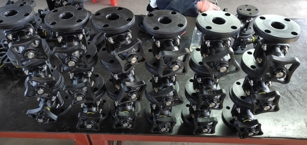
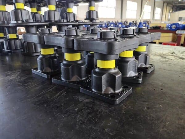
The structure of the diaphragm valve is very different from the general valve. It is a new type of valve and a special form of cut-off valve. Its opening and closing part is a diaphragm made of soft material. The inner cavity of the bonnet and the driving part are separated and are now widely used in various fields. Commonly used diaphragm valves include rubber-lined diaphragm valves, fluorine-lined diaphragm valves, unlined diaphragm valves, and plastic diaphragm valves.
Diaphragm valve is equipped with a flexible diaphragm or combined diaphragm in the valve body and bonnet, and its closing part is a compression device connected with the diaphragm. The valve seat can be a weir shape or a pipe wall that directly leads to the flow channel. The advantage of the diaphragm valve is that its operating mechanism is separated from the medium passage, which not only ensures the purity of the working medium, but also prevents the possibility of the medium in the pipeline from impacting the working parts of the operating mechanism. In addition, there is no need to use any form of separate seal at the valve stem, unless it is used as a safety facility in the control of hazardous media. In the diaphragm valve, since the working medium is only in contact with the diaphragm and the valve body, both of which can use a variety of different materials, the valve can ideally control a variety of working media, especially suitable for chemically corrosive or suspended particles medium. The working temperature of the diaphragm valve is usually limited by the materials used in the diaphragm and the valve body lining, and its working temperature range is about -50 to 175°C. The diaphragm valve has a simple structure, consisting of three main parts: the valve body, the diaphragm and the valve head assembly. The valve is easy to quickly disassemble and repair, and the replacement of the diaphragm can be completed on site and in a short time.
Own characteristics
1. The fluid resistance is small.
2. It can be used for the medium containing hard suspended solids; since the medium only contacts the valve body and the diaphragm, no packing is needed, there is no problem of packing leakage, and there is no possibility of corrosion to the valve stem.
3. It is suitable for corrosive, viscous and slurry medium.
4. Cannot be used in high pressure occasions.
Working principle and composition
The diaphragm valve uses a corrosion-resistant lining body and a corrosion-resistant diaphragm instead of the valve core assembly, and the movement of the diaphragm is used for adjustment. The valve body material of the diaphragm valve is made of cast iron, cast steel, or cast stainless steel, and lined with various corrosion-resistant or wear-resistant materials, and the diaphragm material is made of rubber and polytetrafluoroethylene. The lining diaphragm has strong corrosion resistance and is suitable for the adjustment of strong corrosive media such as strong acid and strong alkali.
The diaphragm valve has simple structure, low fluid resistance, larger flow capacity than other types of valves of the same specification, no leakage, and can be used for the adjustment of high viscosity and suspended particulate media. The diaphragm isolates the medium from the upper cavity of the valve stem, so there is no packing medium and no leakage. However, due to the limitation of the diaphragm and lining materials, the pressure resistance and temperature resistance are poor, and it is generally only suitable for the nominal pressure of 1.6MPa and below 150°C.
The flow characteristic of the diaphragm valve is close to the quick opening characteristic, which is approximately linear before 60% of the stroke, and the flow rate after 60% does not change much. Pneumatic diaphragm valves can still be equipped with feedback signals, limiters and positioners to meet the needs of automatic control, program control or flow adjustment. The feedback signal of the pneumatic diaphragm valve adopts non-contact sensing technology. This product uses a membrane type propulsion cylinder instead of a piston cylinder, eliminating the disadvantage of easy damage to the piston ring, causing leakage and inability to push the valve to open and close. When the air source fails, the handwheel can still be operated to open and close the valve.
Structure Classification
Diaphragm valves can be divided into six types according to their structure: house type, DC type, cut-off type, straight-through type, gate type and right-angle type; the connection form is usually flange connection; according to the driving mode, it can be divided into three types: manual, electric and pneumatic , The pneumatic drive is divided into three types: normally open, normally closed and reciprocating.
- Weir type
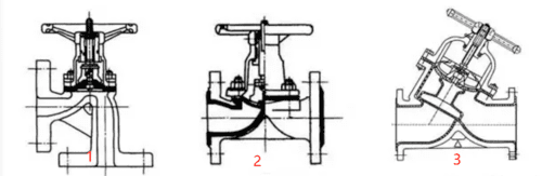
The valve body is lined. Diaphragm valve body lining is to better exert its corrosion resistance characteristics. as shown in picture 2.
This type of structure, in addition to the straight-through type, can also be made into a right-angle type, as shown in Figure 1.
2. Straight-through
Its structure and shape are similar to that of a globe valve.
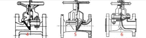
This type of diaphragm valve has a larger fluid resistance than a weir diaphragm valve, but it has a large sealing area and good sealing performance, which is suitable for pipelines with high vacuum. As shown in Figure 5 and Figure 6.
- DC type
Its structure is similar to gate valve. The gate diaphragm valve has the least fluid resistance and is suitable for conveying viscous materials. As shown in Figure 3 and Figure 4.
Installation and maintenance
1. Before installing the diaphragm valve, carefully check whether the operating conditions of the pipeline are consistent with the scope of use specified by this valve, and clean the inner cavity to prevent dirt from jamming or damaging the sealing parts.
2. Do not apply grease or oil on the surface of the rubber lining and the rubber diaphragm to prevent the rubber from swelling and affecting the service life of the diaphragm valve.
3. Handwheels or transmission mechanisms are not allowed to be used for lifting, and collisions are strictly prohibited.
4. When manually operating the diaphragm valve, do not use auxiliary levers to prevent excessive torque from damaging the drive components or sealing parts.
5,Diaphragm valves should be stored in a dry and ventilated room. Stacking is strictly prohibited. Both ends of the stock diaphragm valve must be sealed, and the opening and closing parts should be in a slightly open state.
Attention
Installation.
1 Applicable safety regulations must be complied with.
2 Ensure that the pipeline is free of impurities before the valve is installed, otherwise it will cause damage to the valve.
3 Connect the valve and pay attention to aligning with the pipeline.
4 For all valves, the actuator must be disassembled before the welding process is performed on the valve body.
5 When replacing the diaphragm, it is necessary to maintain the open connection between the diaphragm and the sealing surface, and then separate the diaphragm from the sealing surface.
For air-to-open function valves:
1) Vent the actuator to lift the diaphragm away from the sealing surface.
2) Cross disassemble the four screws on the valve body to separate the actuator from the valve seat, cut off the air source, and replace the diaphragm.
3) Vent the actuator to retract the diaphragm.
4) Align the sealing surface of the diaphragm and the valve seat, cross-install the fixing screws, and repeat the ventilating movement several times.
5) After closing the diaphragm valve for leak testing, it can be used normally.
For air-to-close function valves:
1) Cut off the air source of the actuator and lift the diaphragm away from the sealing surface.
2) Cross disassemble the screws on the valve body to separate the actuator from the valve seat, ventilate, and replace the diaphragm.
3) When the diaphragm is stowed, align the diaphragm and the sealing surface on the valve seat, and install the fixing screws crosswise.
5) Repeated ventilating activities several times, after closing the diaphragm valve for leak testing, it can be used normally.
For double-acting function valves:
1) Cut off the air source and lift the diaphragm away from the sealing surface.
2) Cross disassemble the four screws on the valve body to separate the actuator from the valve seat, cut off the air source of the lower cylinder, inflate the upper cylinder, and replace the diaphragm.
3) Inflate the lower cylinder to retract the diaphragm.
4) Align the sealing surface of the diaphragm and the valve seat, cross-install the fixing screws, and repeat the ventilating movement several times.
5) After closing the diaphragm valve for leak testing, it can be used normally
Diaphragm valve application
Diaphragm valve is suitable for solid and easily polluted inert media. Diaphragm valves are mainly used in the biopharmaceutical and food industries; as well as industrial water treatment in electric power, chemical, electroplating, and other industries. They are also used in the production of semiconductor wafers. Diaphragm valves are especially suitable for conveying corrosive and viscous products. Fluids, such as mud, food, medicine, fibrous adhesive, etc.
Diaphragm valves are used in pure water, ultra-pure water, etc.
Diaphragm valve can be driven by pneumatic or hydraulic pressure, and can complete automatic and semi-automatic operation with various types of control.
Because the diaphragm material is commonly used natural rubber, neoprene, nitrile rubber, isobutyl rubber, fluorinated rubber and polyfluoroethylene propylene plastic, etc. The disadvantage of the diaphragm valve is that the pressure resistance is not high, generally within 6kgf/cm2 (0.6MPa); the temperature resistance performance is also limited by the diaphragm, generally only 60~120℃, the highest (fluorine rubber) does not exceed 180℃ .