Purpose and main performance parameters
1. Rubber-lined diaphragm valves are suitable for general corrosive fluid pipelines whose working temperature is ≤120°C as opening and closing parts to control the flow of the medium.
Main performance parameters:
| DN(mm) | Working Pressure (MPa) | Test Pressure | Test Pressure | Test Temperature |
| Sealing | Strength | |||
| 25~150 | 0.6 | 0.66 | 0.9 | Room temperature |
| 25~200 | 1.0 | 1.1 | 1.5 | Room temperature |
Principle of action and structural characteristics
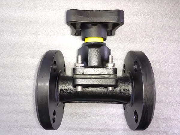
1. This valve is composed of valve body, bonnet, valve stem, valve disc, diaphragm and driving parts.
2. The opening and closing of the valve is achieved by rotating the hand wheel. When the handwheel is rotated clockwise, the valve will drop to cut off the passage; otherwise, the valve will open.
3. When the diaphragm valve is used in the water vapor pipeline with the working temperature ≤120℃, the material of the diaphragm should be heat-resistant rubber, and indicate it when ordering.
Maintenance and installation
1. The valve should be stored in a dry and ventilated room, and it is strictly forbidden to stack them.
2. Both ends of the passage of the inventory valve must be sealed to prevent dust or other matter entering the inner cavity and damaging the sealing parts. And should avoid contact with oil or other flammable materials.
3. The metal processing surface of this valve should be cleaned and coated with anti-rust oil. The oil cup needs to be filled with lubricating grease frequently.
4. Do not paint grease or oil on the surface of the rubber lining or rubber diaphragm, so as to avoid rubber swelling and affect the service life of the valve.
5. During storage or during non-use, the handwheel should be rotated counterclockwise to keep the valve in a slightly open state to prevent the diaphragm from losing its elasticity due to long-term pressure.
6. During transportation or installation, the sling shall not be tied to the handwheel or valve stem. And it is strictly prohibited to collide with other metal or hard objects to prevent damage to the parts and rubber lining.
7. Before installation, carefully check whether the operating conditions of the pipeline and the medium are consistent with the scope of application of the valve, to avoid unnecessary losses due to improper selection, and even accidents.
8. Except that this valve is not suitable for use in vacuum pipelines, it can be installed at any position of the pipeline for two-way flow, but it should be convenient for operation and maintenance.
9. Before installation, clean the inner cavity of the valve to prevent dirt from jamming or damaging the sealing parts, and check whether the connecting bolts of each part are evenly distributed and tightened.
10. During operation, the parts in contact with the medium must be checked frequently, and the vulnerable parts should be replaced regularly according to the actual usage.
11. When replacing the diaphragm, be careful not to overtighten or loosen the diaphragm.
12. If this valve is used in intermittent operation pipelines, during the period of non-use, the parts in contact with the medium should be cleaned to extend the service life.
13. When manually operating the valve, do not use the auxiliary lever to open and close the valve, so as to avoid excessive torque and damage the driving parts or sealing parts.
14. Valves that have been overhauled can only be installed after they have passed the leak test according to the relevant test regulations before being used.
Possible failures and elimination methods
| Possible failure | Cause | Remedy |
| Handwheel rotation is not flexible | Δ Dirt or thread damage is accumulated on the valve stem ΔStem nut is worn or cracked ΔBending stem ΔBearing cracks | ΔRemove dirt or trim threads and inject lubricant ΔReplace the stem nut ΔCorrection or replacement of valve stem ΔReplace the bearing |
| Leakage at the connection between the valve body and the bonnet | ΔThe connecting bolts are not evenly tightened ΔThe valve body rubber lining layer is damaged | ΔTighten uniformly ΔThe valve body should be replaced |
| Leakage between the sealing surfaces | Δ Dirt deposits between the sealing surfaces ΔSlight damage to the sealing surface ΔThe diaphragm is too tight or too loose ΔThe diaphragm is severely corroded or cracked ΔThe sealing surface lining rubber layer is damaged | ΔRemove dirt and do not damage the sealing surface ΔShould be trimmed according to the original curved surface ΔAdjust the tightness of the diaphragm appropriately ΔReplace the diaphragm ΔThe valve body should be replaced |